Outdoor electrical outlets are invaluable for powering lawn equipment, holiday lights, and other seasonal decorations. However, ensuring these outlets are properly installed and protected from the elements is crucial for both safety and functionality. Improperly installed outdoor receptacles pose a significant risk of electric shock, especially in wet conditions, leading to potential injury or even fatality. A Ground Fault Circuit Interrupter (GFCI) outlet is designed to mitigate these risks by instantly cutting off power if a ground fault is detected, protecting both people and equipment. Therefore, understanding the proper installation techniques is paramount.
This guide provides a comprehensive, step-by-step process for safely installing an outdoor GFCI receptacle. We will walk you through each stage, from initial planning and preparation to final testing and connection, ensuring you can confidently complete this project and enjoy the benefits of a safe and reliable outdoor power source. Let's begin!
Preparation and Safety Guidelines
- Weatherproof GFCI receptacle kit
- Mounting block
- Oscillating tool
- Measuring tape
- Drill
- Screwdrivers (Phillips and 5/16 nut driver)
- Linemans pliers
- Wire strippers
- Silicone sealant
- Duct sealant
- Non-contact voltage tester
- Romex 14/2 wire
- Always turn off the power at the breaker box before beginning any work. Failure to do so could result in serious injury or death.
- Use appropriate personal protective equipment (PPE), including safety glasses and work gloves, throughout the installation process.
- Ensure the receptacle is installed according to local electrical codes and regulations. Improper installation can lead to fire hazards and malfunction.
Step-by-Step Instructions
Planning and Preparation
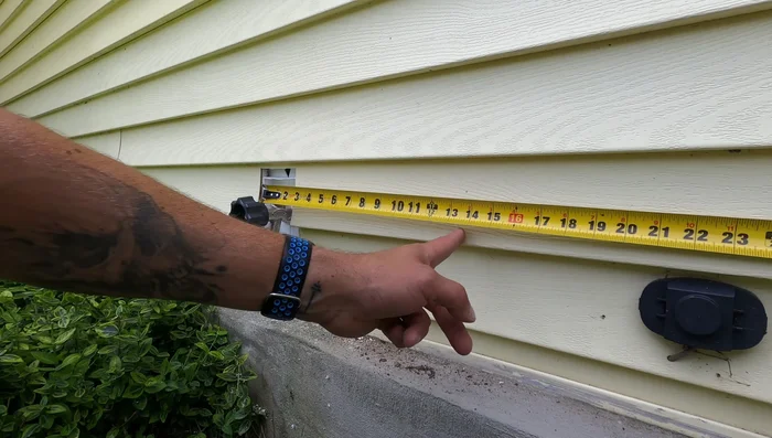
- Measure and mark the location for the receptacle. Ensure it aligns with existing outdoor fixtures for a clean look.

Planning and Preparation Mounting Block Installation
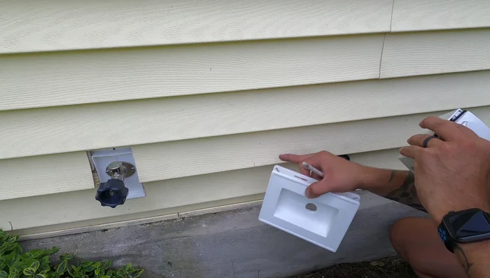
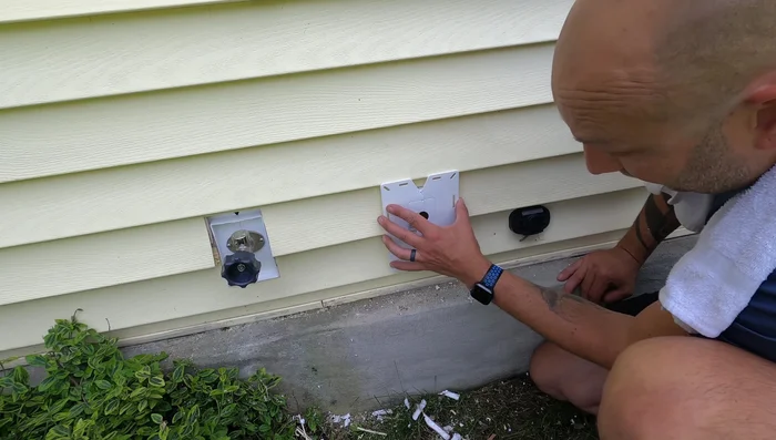
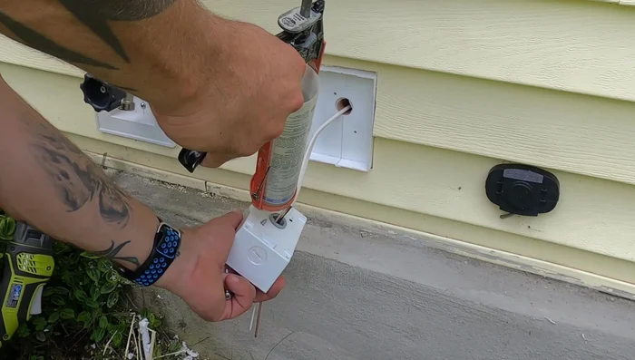
- Cut the hole for the mounting block using an oscillating tool. Ensure enough space for expansion and contraction of the siding.
- Fit the mounting block into the hole, ensuring sufficient clearance for siding movement. Make adjustments as needed.
Mounting Block Installation Wiring the Receptacle
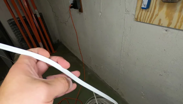
- Run Romex 14/2 wire from the electrical panel to the outdoor location. Use appropriate strain relief in the receptacle box and seal any gaps with silicone to prevent water intrusion.
- Mount the receptacle box, feeding the wire through. Seal around the box exterior with duct sealant to prevent air infiltration.
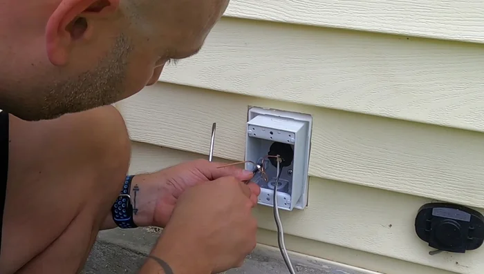
- Install the bonding jumper (green screw) to connect the ground to the metal box.
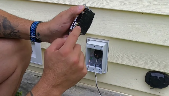
- Connect the wires to the GFCI receptacle (line and load sides). Black wire goes to the brass terminal, white to the silver terminal, and green/bare copper to the ground screw.
Wiring the Receptacle Electrical Panel Work
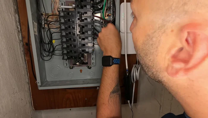
- Run the wire to the electrical panel. This step requires knowledge of electrical safety and may require a licensed electrician.
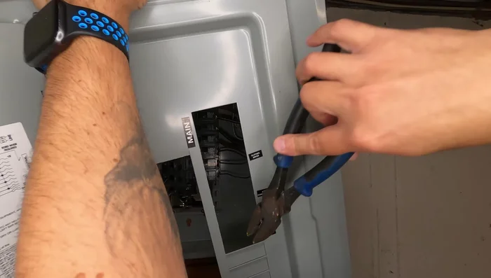
- Install the new breaker in the panel. Ensure the breaker is off before making connections. Use the same manufacturer's breaker as the panel.
- Connect the receptacle wires to the breaker. Secure the neutral and ground to the same bus bar, and connect the hot wire to the breaker.
Electrical Panel Work Testing and Finalization
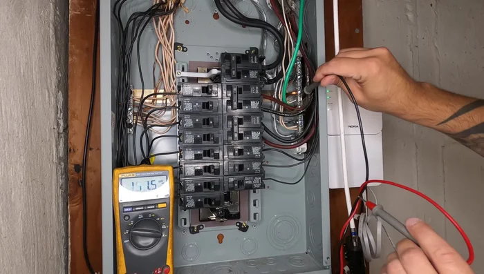
- Test the outlet using a non-contact voltage tester to ensure power is present.
- Replace the electrical panel cover and label the new breaker.
Testing and Finalization


Read more: How to Wire Your Garage Door Opener: A Step-by-Step Guide
Tips
- Use an oscillating tool for a quick and clean cut in the siding.
- Allow for expansion and contraction of the siding when installing the mounting block.
- Use silicone sealant around the receptacle box to prevent water intrusion.
- Use duct sealant to seal any gaps around the wire entry point to prevent air leakage.
- Always turn off the breaker before working with the wiring in the electrical panel.