Leviton offers a range of programmable timers designed to enhance convenience and energy efficiency in your home. Whether you're aiming to automate lighting schedules, control appliances remotely, or simply add a layer of security with timed illumination, the VPT24 Programmable Timer and the LTB Series Countdown Timer Switches provide versatile solutions. These user-friendly devices offer a balance of advanced features and straightforward operation, making them suitable for both seasoned DIY enthusiasts and beginners alike. Understanding their installation is key to unlocking their full potential.
This guide will walk you through the installation process for both the Leviton VPT24 and LTB series timers, covering everything from initial preparation to final testing. We'll provide clear, step-by-step instructions with accompanying visuals to ensure a smooth and successful installation, allowing you to effortlessly integrate these timers into your home's electrical system. Let's get started!
Preparation and Safety Guidelines
- Flathead screwdriver
- Phillips head screwdriver
- Electrician pliers
- Wire stripper
- Electrical tape
- Handheld voltage tester
- Properly sized wire connectors
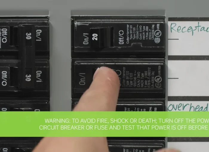
- Always turn off the power at the breaker box before beginning any wiring work. Failure to do so could result in serious injury or death.
- Verify the voltage of your circuit matches the timer's specifications. Using an incompatible voltage can damage the timer and/or cause a fire.
- If you are not comfortable working with electrical wiring, consult a qualified electrician. Improper installation can lead to safety hazards and void warranties.
Step-by-Step Instructions
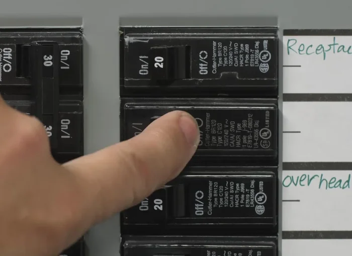
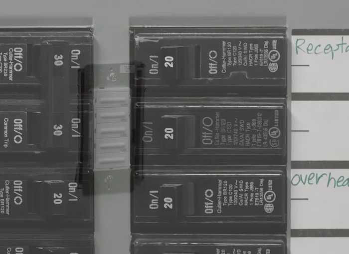
Safety First: Power Off and Verification
- Turn off the power at the circuit breaker and use a voltage tester to ensure the power is completely off.

Safety First: Power Off and Verification Wire Identification and Preparation
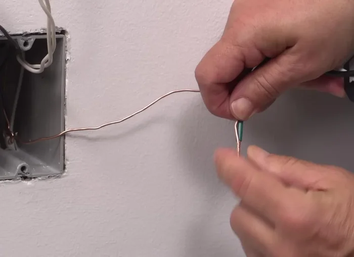
- Identify the hot wire using a voltage tester. Label the hot wire with electrical tape.
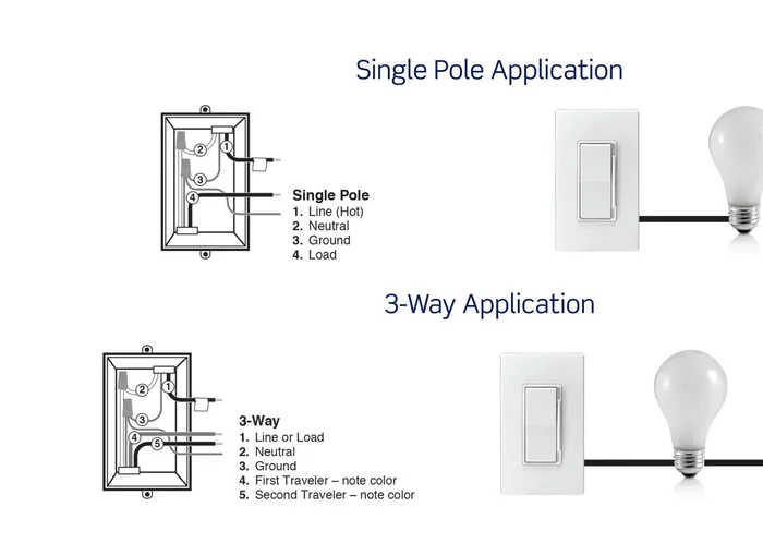
- Identify whether the wiring application is single-pole or three-way. (This example shows a single-pole application.)
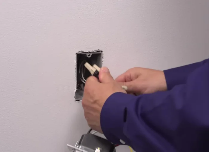
- Prepare the wires for installation by removing a small piece of insulation from the pigtail leads on the timer switch and twisting the exposed stranded copper wiring clockwise.
Wire Identification and Preparation Grounding and Wiring Connections
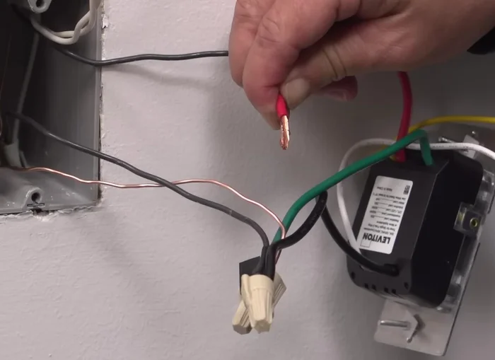
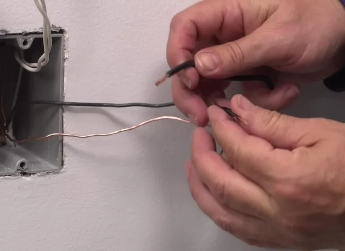
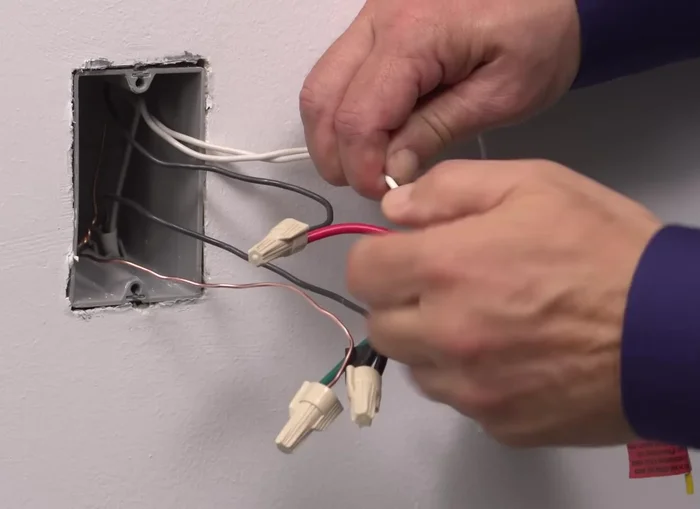
- Connect the green ground lead to the green or bare copper wire in the wall box using a wire connector.
- Connect the line wallbox wire to the black lead and the load wallbox wire to the red lead using wire connectors.
- Connect the neutral wallbox wire to the white lead using a wire connector.
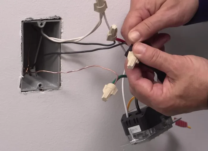
Grounding and Wiring Connections Securing Wires and Mounting
- Dress the terminated wires with electrical tape to ensure stability.
- Position all wires in the wall box, ensuring the word "top" is facing up on the device. Partially screw in the mounting screws.
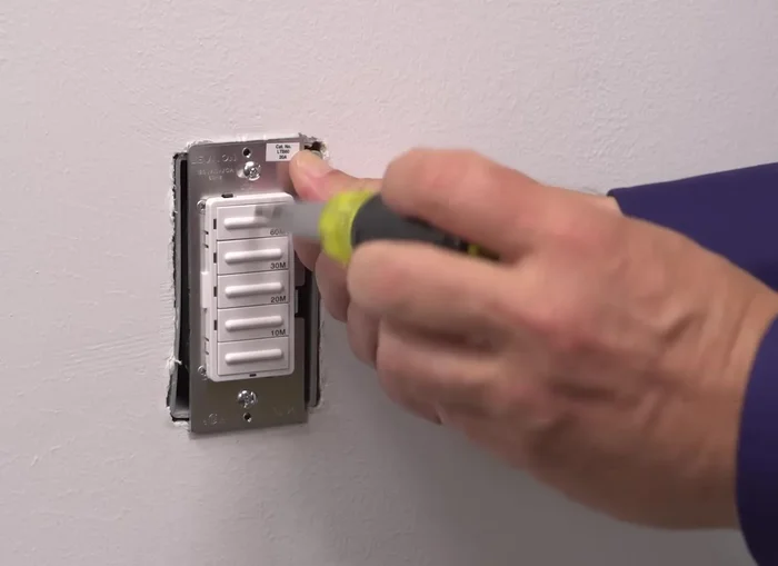
Securing Wires and Mounting Testing and Final Installation
- Restore power at the circuit breaker and test the device. Press any timer button to turn the load on.
- Turn off power, tighten mounting screws, and attach the wall plate. Restore power.
Testing and Final Installation
Read more: Installing an Outdoor GFCI Receptacle: A Step-by-Step Guide
Tips
- If unsure about any part of the instructions, contact an electrician.
- Always turn off the power at the circuit breaker before working with electrical wiring.
- Use a voltage tester to verify that the power is off before and after working on the wiring.
- Twisting the exposed stranded copper wiring clockwise before connecting helps secure it in the wire connector.
- Ensure that the ends of the wires from the wall box are straight and stripped approximately 5/8 of an inch before connecting.